How to use the Tinkercad builds
Start with the screenshot so you know where the parts go.
Then wire the parts in the same order as the steps. Add the sketch last.
Use the picture first
Do not start with code if the wiring is not clear yet.
Name the pins
Write the pin numbers down while you wire them.
Test one thing
Check one LED, one sensor, or one motor before you test the full project.
LED Dice
This is a fun starter circuit. It mixes button input, random numbers, and LED patterns.
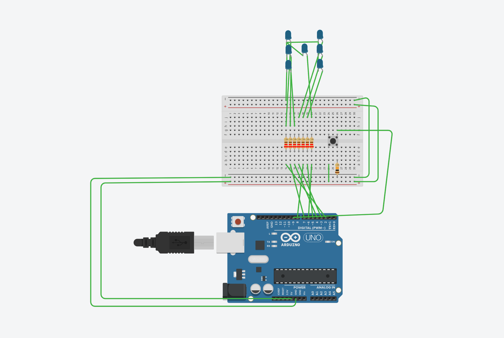
Wire steps
- Wire the LEDs to digital pins 2 to 8 through resistors.
- Wire the push button to pin 9 and use
INPUT_PULLUPin code. - Paste the sketch into Tinkercad Code or the Arduino IDE.
- Press the button to roll a new number.
Parts
- Arduino Uno
- 7 LEDs
- 7 resistors
- 1 push button
- Breadboard and jumper wires
Quick test
- Every button press should light one pattern from 1 to 6.
- The LEDs should turn off before the next pattern is shown.
FILE: sketch.ino
const int buttonPin = 9;

int leds[7] = {2, 3, 4, 5, 6, 7, 8};
// 0=LH, 1=PH, 2=LD, 3=PD, 4=STRED, 5=LS, 6=PS

int lastButtonState = 0;

void setup() {
  for (int i = 0; i < 7; i++) {
    pinMode(leds[i], OUTPUT);
  }

  pinMode(buttonPin, INPUT);
  randomSeed(analogRead(A0));
}

void loop() {

  int buttonState = digitalRead(buttonPin);

  if (buttonState == HIGH && lastButtonState == LOW) {
    int cislo = random(1, 7);
    zobrazCislo(cislo);
    delay(200);
  }

  lastButtonState = buttonState;
}

void zhasni() {
  for (int i = 0; i < 7; i++) {
    digitalWrite(leds[i], LOW);
  }
}

void zobrazCislo(int n) {

  zhasni();

  switch (n) {

    case 1: // střed
      digitalWrite(leds[4], HIGH);
      break;

    case 2: // levý horní + pravý dolní
      digitalWrite(leds[0], HIGH);
      digitalWrite(leds[3], HIGH);
      break;

    case 3: // levý horní + střed + pravý dolní
      digitalWrite(leds[0], HIGH);
      digitalWrite(leds[4], HIGH);
      digitalWrite(leds[3], HIGH);
      break;

    case 4: // všechny rohy
      digitalWrite(leds[0], HIGH);
      digitalWrite(leds[1], HIGH);
      digitalWrite(leds[2], HIGH);
      digitalWrite(leds[3], HIGH);
      break;

    case 5: // rohy + střed
      digitalWrite(leds[0], HIGH);
      digitalWrite(leds[1], HIGH);
      digitalWrite(leds[2], HIGH);
      digitalWrite(leds[3], HIGH);
      digitalWrite(leds[4], HIGH);
      break;

    case 6: // rohy + levý střed + pravý střed
      digitalWrite(leds[0], HIGH);
      digitalWrite(leds[1], HIGH);
      digitalWrite(leds[2], HIGH);
      digitalWrite(leds[3], HIGH);
      digitalWrite(leds[5], HIGH);
      digitalWrite(leds[6], HIGH);
      break;
  }
}LED Sequence Prototype
If you need one clear loop task in Tinkercad, this is a good choice.
Wire steps
- Connect the LEDs to pins 2 to 6 through resistors.
- Paste the code and start the simulation.
- Watch the light move from left to right and back again.
Parts
- Arduino Uno
- 5 LEDs
- 5 resistors
- Breadboard
Quick test
- The LEDs should turn on one after another, not all at once.
- The direction should reverse after the last LED.
FILE: sketch.ino
const int leds[] = {2, 3, 4, 5, 6};
void setup() {
for (int i = 0; i < 5; i++) {
pinMode(leds[i], OUTPUT);
}
}
void loop() {
for (int i = 0; i < 5; i++) {
lightOne(i);
}
for (int i = 3; i > 0; i--) {
lightOne(i);
}
}
void lightOne(int index) {
for (int i = 0; i < 5; i++) {
digitalWrite(leds[i], i == index ? HIGH : LOW);
}
delay(180);
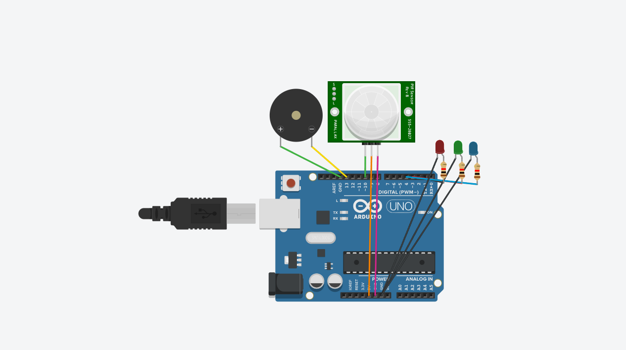
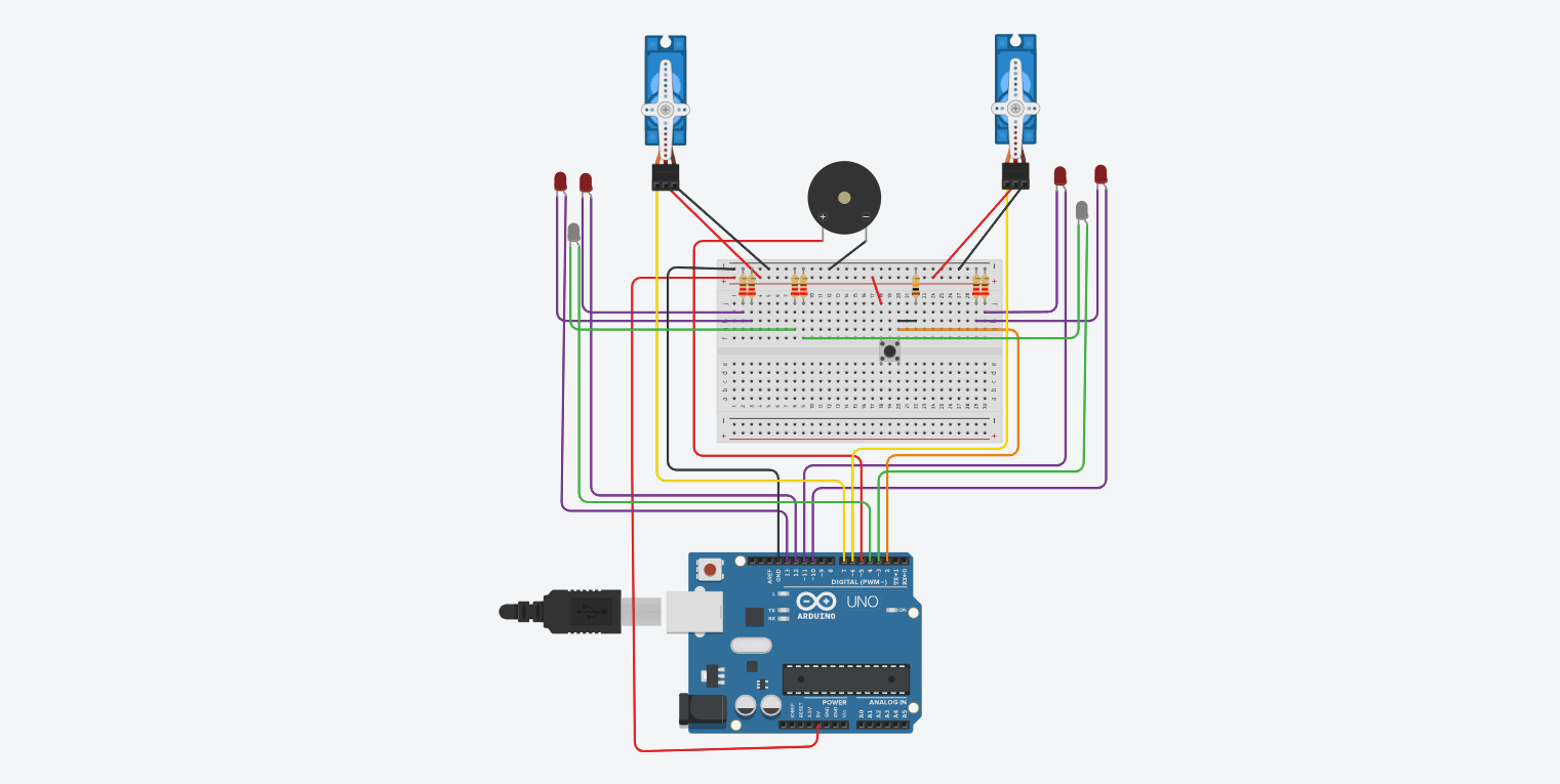
}Motion Alarm with Buzzer and Servo
This project mixes a sensor, an actuator, and a sound output in one build.
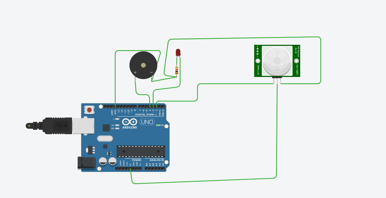
Wire steps
- Connect the PIR output to pin 2.
- Connect the buzzer to pin 8.
- Connect the servo signal wire to pin 9.
- Paste the code and start the simulation.
- Trigger the PIR sensor to test the alarm.
Parts
- Arduino Uno
- PIR motion sensor
- Piezo buzzer
- Servo motor
Quick test
- When motion is detected, the buzzer should beep and the servo should move.
- When there is no motion, the buzzer should stop and the servo should return.
FILE: sketch.ino
int pir_pin = 2;
int led_pin = 3;
int buzzer_pin = 4;
#include <Servo.h>     //zahrnutí knihovny pro ovládání servo motoru
Servo myservo;         //každý motor má svou instanci třídy Servo
int pos = 0;           //proměnná obsahující pozici motoru (úhel natočení)
void setup()
{
 pinMode(pir_pin, INPUT);
 pinMode(led_pin, OUTPUT);
 pinMode(buzzer_pin, OUTPUT);
   myservo.attach(7);
 Serial.begin(9600);

}

void loop()
{
  if(digitalRead(pir_pin) == HIGH)
   {
  	digitalWrite(led_pin, HIGH);
    digitalWrite(buzzer_pin, HIGH);
    Serial.println("Detectado");
    for(pos = 0; pos <= 90; pos += 1) //je od úhlu 0 do úhlu 180
  {
    myservo.write(pos);  //natočení motoru na aktuální úhel
    delay(15);           //chvilka čekání než se motor natočí
  }
   }
   else{
    digitalWrite(led_pin, LOW);
    digitalWrite(buzzer_pin, LOW);
    Serial.println("No Detectado");
     for(pos = 90; pos >= 0; pos -= 1) //je od úhlu 180 zpět do úhlu 0
  {
    myservo.write(pos);  //natočení motoru na aktuální úhel
    delay(15);           //chvilka čekání než se motor natočí

  }
   }
}
Running Lights with Potentiometer Control
The potentiometer changes the timing, which makes this more useful than a fixed chaser.
Wire steps
- Wire the LEDs to pins 2 to 5.
- Wire the potentiometer middle pin to A0.
- Read the analog value and map it to a delay range.
- Run the sequence and adjust the knob.
Parts
- Arduino Uno
- 4 LEDs
- 4 resistors
- 1 potentiometer
Quick test
- Turning the potentiometer should change the speed.
- The LED order should still stay the same.
FILE: sketch.ino
const int leds[] = {2, 3, 4, 5};
const int potPin = A0;

void setup() {
  for (int i = 0; i < 4; i++) {
    pinMode(leds[i], OUTPUT);
  }
}

void loop() {
  int sensorValue = analogRead(potPin);
  int waitTime = map(sensorValue, 0, 1023, 60, 600);

  for (int i = 0; i < 4; i++) {
    digitalWrite(leds[i], HIGH);
    delay(waitTime);
    digitalWrite(leds[i], LOW);
  }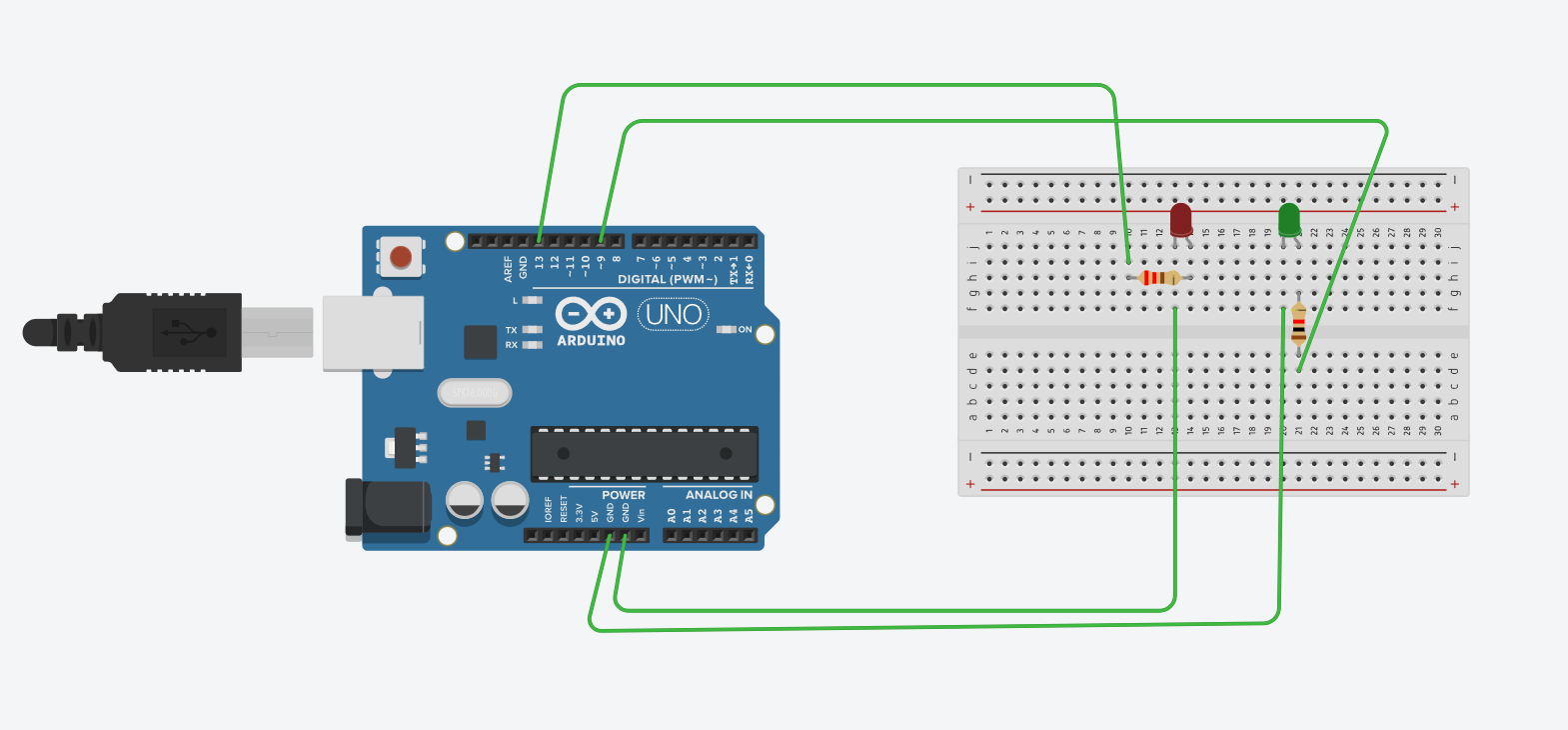
}Motion Alarm with LEDs
This is a lighter version of the buzzer-plus-servo alarm and is easier for beginners.
Wire steps
- Wire the PIR to pin 2.
- Wire the green LED to pin 8 and the red LED to pin 9.
- Paste the sketch and start the simulation.
- Trigger motion to swap the LED states.
Parts
- Arduino Uno
- PIR motion sensor
- 1 green LED
- 1 red LED
- 2 resistors
Quick test
- No motion should show the green LED.
- Motion should switch to the red LED.
FILE: sketch.ino
const int pirPin = 2;
const int greenLed = 8;
const int redLed = 9;

void setup() {
  pinMode(pirPin, INPUT);
  pinMode(greenLed, OUTPUT);
  pinMode(redLed, OUTPUT);
}

void loop() {
  int motion = digitalRead(pirPin);

  if (motion == HIGH) {
    digitalWrite(redLed, HIGH);
    digitalWrite(greenLed, LOW);
  } else {
    digitalWrite(redLed, LOW);
    digitalWrite(greenLed, HIGH);
  }

  delay(100);
}Two Blinking LEDs
This is one of the fastest Arduino exercises to build and check.
Wire steps
- Wire one LED to pin 2 and the other to pin 3.
- Paste the sketch.
- Run the simulation and watch them alternate.
Parts
- Arduino Uno
- 2 LEDs
- 2 resistors
Quick test
- Only one LED should be on at a time.
- The pattern should repeat forever.
FILE: sketch.ino
// C++ code
//
void setup()
{
  pinMode(13, OUTPUT);
  pinMode(9, OUTPUT);
}

void loop()
{
  // your led will glow/on
  digitalWrite(13, HIGH);
  // your led glow for 500 miliseconds / half seconds
  delay(500); // Wait for 500 millisecond(s)
  digitalWrite(13, LOW);
  delay(500); // Wait for 500 millisecond(s)
  digitalWrite(9, HIGH);
  delay(500); // Wait for 500 millisecond(s)
  digitalWrite(9, LOW);
  delay(500); // Wait for 500 millisecond(s)
}Light-Controlled Motor Prototype
This prototype is useful for talking about thresholds and transistor-driven outputs.
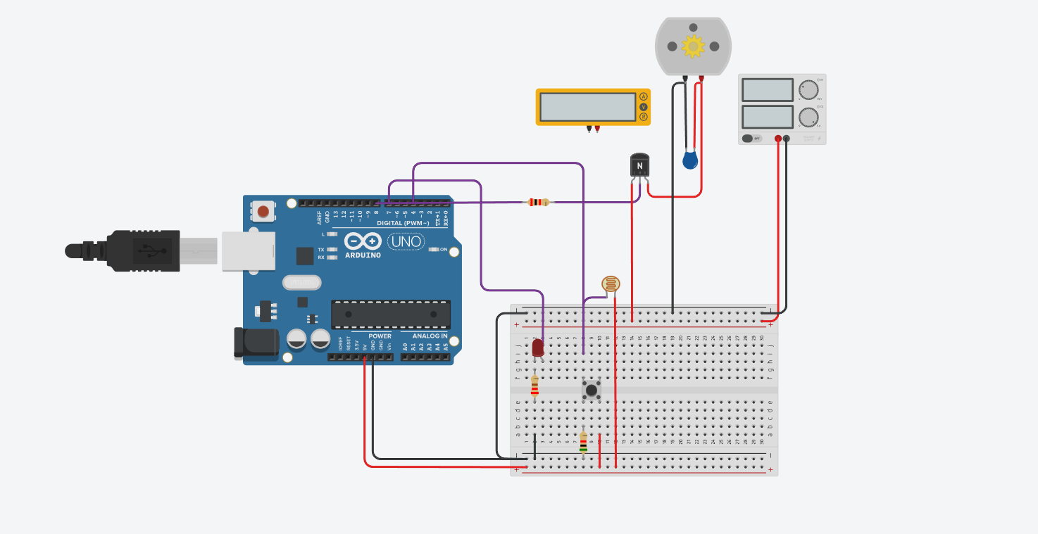
Wire steps
- Build the photoresistor voltage divider to A0.
- Use a transistor for the motor output on pin 9.
- Paste the sketch and adjust the threshold if needed.
- Cover the photoresistor to test the dark condition.
Parts
- Arduino Uno
- Photoresistor and fixed resistor
- DC motor with transistor driver
- External motor supply if needed
Quick test
- In bright light the motor should stay off.
- In darker light the motor should switch on.
FILE: sketch.ino
// C++ code

void setup()
{
  pinMode(7, OUTPUT);   // LED přímo na Arduinu
  pinMode(8, OUTPUT);   // ovládání tranzistoru
  pinMode(4, INPUT);    // tlačítko (pull-down)
}

void loop()
{
  int inputValue = digitalRead(4);

  if (inputValue == HIGH) {
    digitalWrite(7, HIGH);   // zapni 1. LED
    digitalWrite(8, HIGH);   // sepni tranzistor => 2. motor jede
  } else {
    digitalWrite(7, LOW);    // zhasni 1.led
    digitalWrite(8, LOW);    // vypni tranzistor => 2. motor jede
  }
}
Motor Encoder Speed Reader
This one is a bit more advanced. It is still practical if you keep the reading time fixed.
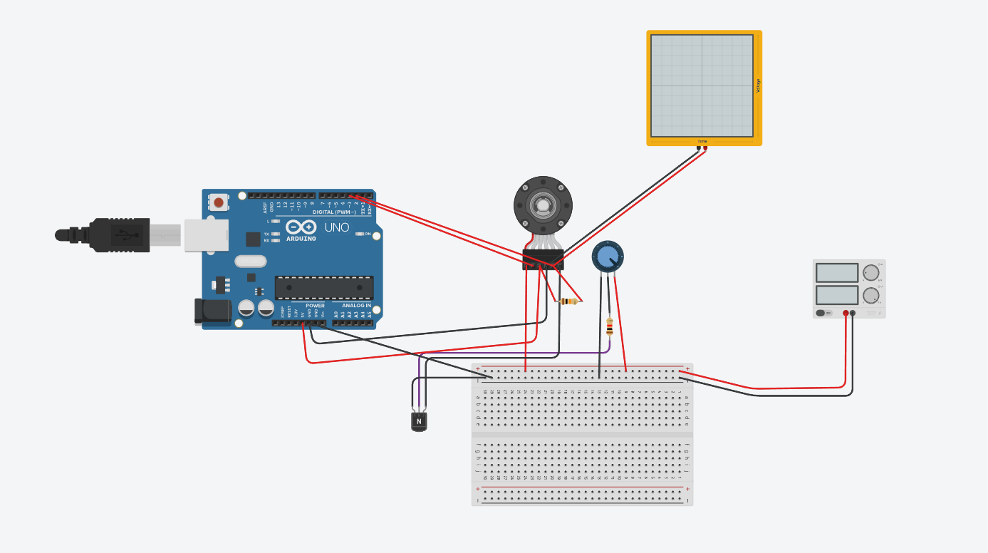
Wire steps
- Connect the encoder output to pin 2 so you can use an interrupt.
- Paste the sketch and open the Serial Monitor.
- Run the motor and read the pulse count each second.
Parts
- Arduino Uno
- Motor with encoder output
- Wires for signal and power
Quick test
- The Serial Monitor should print pulse counts again and again.
- If the motor stops, the count should drop close to zero.
FILE: sketch.ino
const int encoderPinA = 2;
const int encoderPinB = 3;

volatile long encoderCount = 0;

unsigned long lastTime = 0;
const int interval = 100; // ms (měřící okno)

void setup() {
  Serial.begin(9600);

  pinMode(encoderPinA, INPUT_PULLUP);
  pinMode(encoderPinB, INPUT_PULLUP);

  attachInterrupt(digitalPinToInterrupt(encoderPinA), updateEncoder, RISING);

  Serial.println("Mereni rychlosti...");
}

void loop() {

  if (millis() - lastTime >= interval) {

    noInterrupts();
    long pulses = encoderCount;
    encoderCount = 0;   // vynulování pro další měření
    interrupts();

    // pulsy za sekundu
    float pulsesPerSecond = pulses * (1000.0 / interval);

    Serial.print("Pulsy/s: ");
    Serial.println(pulsesPerSecond);

    lastTime = millis();
  }
}

void updateEncoder() {
  if (digitalRead(encoderPinB) == HIGH) encoderCount++;
  else encoderCount--;
}
Railway Crossing Simulation
This project is nice when you want one bigger combined simulation with lights and movement.
Wire steps
- Use pin 2 for the train sensor or button.
- Use pin 9 for the servo.
- Use pins 5, 6, and 7 for the LEDs.
- Paste the code and trigger the crossing event.
Parts
- Arduino Uno
- Servo motor for the gate
- 2 red LEDs
- 1 green LED
- Button or sensor input
Quick test
- When triggered, the gate should move down and the red LEDs should flash.
- After the short wait, the gate should return up and the green LED should come back.
FILE: sketch.ino
#include <Servo.h>

// Define constants for the components
const int buttonPin = 2;   // pushbutton pin
const int ledPin1L = 13;   // 1st Indicator LED Left pin
const int ledPin1R = 12;   // 1st Indicator LED Right pin
const int ledPin2L = 11;   // 2nd Indicator LED Left pin
const int ledPin2R = 10;   // 2nd Indicator LED Right pin
const int whiteLed1 = 4;   // White LED 1
const int whiteLed2 = 3;   // White LED 2
const int servo1Pin = 7;   // 1st Crossing Guard Servo pin
const int servo2Pin = 6;   // 2nd Crossing Guard Servo pin
const int buzzerPin = 5;   // buzzer pin (optional)

// Variables
int buttonState = LOW;
bool sequenceRunning = false;

// Timing variables for slow blinking
unsigned long previousMillis = 0;
const long blinkInterval = 700;  // slow blink every 700 ms
bool whiteLedState = false;

// Create servo objects
Servo myServo1;
Servo myServo2;

void setup() {
    pinMode(buttonPin, INPUT);

    pinMode(ledPin1L, OUTPUT);
    pinMode(ledPin1R, OUTPUT);
    pinMode(ledPin2L, OUTPUT);
    pinMode(ledPin2R, OUTPUT);

    pinMode(whiteLed1, OUTPUT);
    pinMode(whiteLed2, OUTPUT);

    myServo1.attach(servo1Pin);
    myServo2.attach(servo2Pin);

    CrossingGuardsUp();

    pinMode(buzzerPin, OUTPUT);

    Serial.begin(9600);
    Serial.println("Train Crossing Active!");
}

void CrossingGuardsDown() {
    myServo1.write(180);
    myServo2.write(0);
}

void CrossingGuardsUp() {
    myServo1.write(90);
    myServo2.write(80);
}

void FlashLEDs(int flashTimes, int flashDelay, bool beep) {
    for (int ctr1 = 0; ctr1 < flashTimes; ctr1++) {
        digitalWrite(ledPin1L, HIGH);
        digitalWrite(ledPin2R, HIGH);
        digitalWrite(ledPin2L, LOW);
        digitalWrite(ledPin1R, LOW);

        if (beep) digitalWrite(buzzerPin, HIGH);
        delay(flashDelay);
        if (beep) digitalWrite(buzzerPin, LOW);

        digitalWrite(ledPin2L, HIGH);
        digitalWrite(ledPin1R, HIGH);
        digitalWrite(ledPin1L, LOW);
        digitalWrite(ledPin2R, LOW);
        delay(flashDelay);
    }

    digitalWrite(ledPin1L, LOW);
    digitalWrite(ledPin2R, LOW);
    digitalWrite(ledPin2L, LOW);
    digitalWrite(ledPin1R, LOW);
}

void blinkWhiteLEDs() {
    // Only blink when the sequence is NOT running
    if (sequenceRunning) return;

    unsigned long currentMillis = millis();
    if (currentMillis - previousMillis >= blinkInterval) {
        previousMillis = currentMillis;

        whiteLedState = !whiteLedState; // toggle state

        digitalWrite(whiteLed1, whiteLedState);
        digitalWrite(whiteLed2, whiteLedState);
    }
}

void loop() {
    // Always handle white LED blinking
    blinkWhiteLEDs();

    buttonState = digitalRead(buttonPin);

    if (buttonState == HIGH && !sequenceRunning) {
        sequenceRunning = true;
        Serial.println("Train Crossing Button Pressed!");

        // Turn OFF white LEDs during sequence
        digitalWrite(whiteLed1, LOW);
        digitalWrite(whiteLed2, LOW);

        FlashLEDs(7, 200, true);

        CrossingGuardsDown();

        FlashLEDs(20, 200, true);

        CrossingGuardsUp();

        FlashLEDs(5, 200, false);

        // Restart slow blink
        previousMillis = millis();
        whiteLedState = false;
        digitalWrite(whiteLed1, LOW);
        digitalWrite(whiteLed2, LOW);

        sequenceRunning = false;
    }
}
Motion Sensor with Servo Gate
Use a PIR sensor to open a servo gate, keep it open while motion continues, then warn with an LED before the gate closes again.
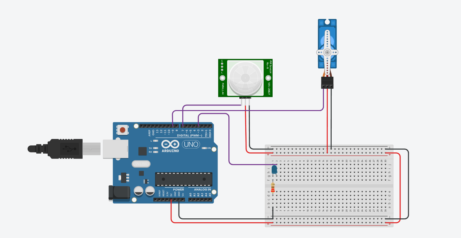
Wire steps
- Connect the PIR signal pin to digital pin 7.
- Connect the warning LED to pin 3 through a resistor.
- Connect the servo signal wire to pin 9 and power it correctly.
- Paste the sketch into Tinkercad Code or Sketch.ino and start the simulation.
Parts
- Arduino Uno
- PIR sensor
- Servo motor
- LED
- 220 ohm resistor
Quick test
- When motion is detected, the servo should open to 90 degrees.
- If motion continues, the open timer should reset.
- Before closing, the LED should turn on and blink as a short warning.
- After the delay, the servo should return to 0 degrees.
FILE: sketch.ino
#include <Servo.h>

Servo myServo;
const int pirPin = 7;    // PIR Signal pin
const int ledPin = 3;   // LED Pin
const int servoPin = 9;  // Servo PWM pin

int pirState = LOW;
int val = 0;
unsigned long motionDetectedTime = 0;
unsigned long timeToClose = 5000; // Time in ms to stay open (5s)
unsigned long warningTime = 3000; // Warning duration (2s)
bool servoOpen = false;

void setup() {
  pinMode(pirPin, INPUT);
  pinMode(ledPin, OUTPUT);
  myServo.attach(servoPin);
  myServo.write(0); // Start closed
  Serial.begin(9600);
}

void loop() {
  val = digitalRead(pirPin);

  if (val == HIGH) { // Motion detected
    digitalWrite(ledPin, LOW); // Turn off warning if motion re-detected
    myServo.write(90); // Open
    if (!servoOpen) {
      Serial.println("Motion detected - Opening");
      servoOpen = true;
    }
    motionDetectedTime = millis(); // Reset timer
  } else {
    // No motion detected, check if we need to start warning
    if (servoOpen && (millis() - motionDetectedTime > (timeToClose - warningTime))) {
      // 2 seconds before closing
      digitalWrite(ledPin, HIGH); // Turn on warning LED

      // Close the servo after the warning
      if (millis() - motionDetectedTime > timeToClose) {
        digitalWrite(ledPin, LOW);
        delay(50);
        digitalWrite(ledPin, HIGH);
        delay(50);
        digitalWrite(ledPin, LOW);
        delay(50);
         digitalWrite(ledPin, LOW);
        delay(50);
        digitalWrite(ledPin, HIGH);
        delay(50);
        digitalWrite(ledPin, LOW);
        delay(50);
        digitalWrite(ledPin, LOW);
        delay(50);
        digitalWrite(ledPin, HIGH);
        delay(50);
        digitalWrite(ledPin, LOW);
        delay(2000);
         myServo.write(0); // Close
        Serial.println("Closing");
        servoOpen = false;
      }
    }
  }
}Temperature Indicator with LEDs
This build is useful when you need one sensor task with thresholds and visible output.
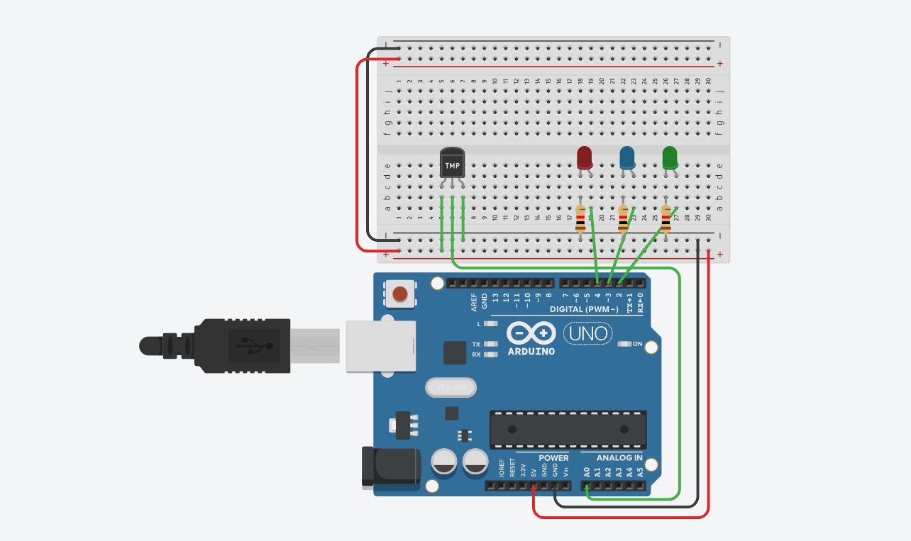
Wire steps
- Wire the temperature sensor output to A0.
- Wire the LEDs to pins 8, 9, and 10.
- Paste the sketch and start the simulation.
- Change the temperature in Tinkercad and watch the LED state change.
Parts
- Arduino Uno
- TMP36 or similar analog temperature sensor
- 3 LEDs
- 3 resistors
Quick test
- Low temperature should light the cold LED.
- Middle temperature should light the normal LED.
- High temperature should light the hot LED.
FILE: sketch.ino
int baselineTemp = 0;
int celsius = 0;
int fahrenheit = 0;

void setup()
{
  pinMode(A0, INPUT);
  Serial.begin(9600);

  pinMode(2, OUTPUT);
  pinMode(3, OUTPUT);
  pinMode(4, OUTPUT);
}

void loop()
{
  baselineTemp = 40;

  celsius = map(((analogRead(A0) - 20) * 3.04), 0, 1023, -40, 125);

   fahrenheit = ((celsius * 9) / 5 + 32);
  Serial.print(celsius);
  Serial.print(" C, ");
  Serial.print(fahrenheit);
  Serial.println(" F");

   if (celsius < baselineTemp) {
    digitalWrite(2, LOW);
    digitalWrite(3, LOW);
    digitalWrite(4, LOW);
  }
  if (celsius >= baselineTemp && celsius < baselineTemp + 10) {
    digitalWrite(2, HIGH);
    digitalWrite(3, LOW);
    digitalWrite(4, LOW);
  }
  if (celsius >= baselineTemp + 10 && celsius < baselineTemp + 20) {
    digitalWrite(2, HIGH);
    digitalWrite(3, HIGH);
    digitalWrite(4, LOW);
  }
  if (celsius >= baselineTemp + 20 && celsius < baselineTemp + 30) {
    digitalWrite(2, HIGH);
    digitalWrite(3, HIGH);
    digitalWrite(4, HIGH);
  }
  if (celsius >= baselineTemp + 30) {
    digitalWrite(2, HIGH);
    digitalWrite(3, HIGH);
    digitalWrite(4, HIGH);
  }
  delay(1000);
}